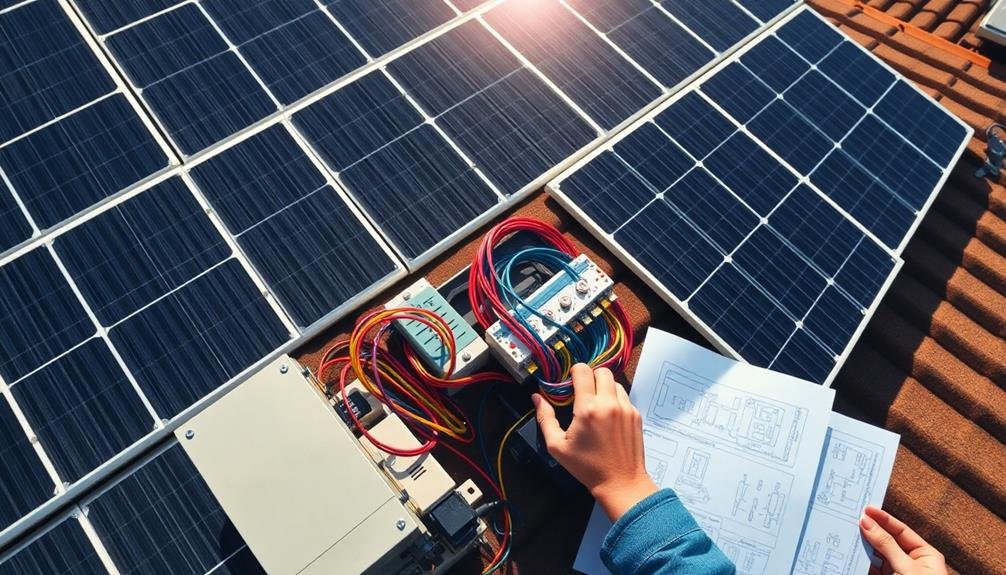
Solar panel wiring diagrams are essential for the successful installation and operation of your renewable energy system. They provide a clear blueprint for connecting components, ensuring proper voltage and current flow, and maximizing power output. You'll use these diagrams to determine the best configuration for your panels, batteries, and inverters, while avoiding common pitfalls like voltage drops or safety hazards. They're vital for troubleshooting issues and planning future expansions. By following a well-designed wiring diagram, you'll optimize your system's performance, reduce energy losses, and maintain safety standards. Understanding these diagrams is key to harnessing the full potential of your solar investment.
Understanding Solar Panel Wiring Basics

Solar panel wiring fundamentals are vital for anyone looking to harness the sun's power effectively. You'll need to understand the basic components and connections to create a functional solar power system.
Start by familiarizing yourself with the key elements: solar panels, charge controllers, batteries, and inverters.
Each solar panel produces direct current (DC) electricity, which must be properly managed and converted for use in your home. You'll connect multiple panels in series or parallel configurations to achieve the desired voltage and current output. Series connections increase voltage, while parallel connections increase current.
Your charge controller regulates the flow of electricity from the panels to the batteries, preventing overcharging and extending battery life. It's important to match your controller's specifications to your system's requirements.
Batteries store excess energy for use when sunlight isn't available. You'll wire them in series or parallel to meet your voltage and capacity needs.
Finally, an inverter converts the DC power from your batteries into alternating current (AC) for use in your home appliances.
Understanding these basics will help you interpret and implement solar panel wiring diagrams effectively, ensuring a safe and efficient solar power system.
Safety Precautions in Diagram Usage

When working with solar panel wiring diagrams, your safety should always be the top priority. Before you begin any installation or maintenance work, verify you're familiar with electrical safety practices and local regulations. Always wear appropriate personal protective equipment, including insulated gloves and safety glasses.
Don't attempt to work on live circuits. Disconnect all power sources and use a multimeter to verify that the system is de-energized before starting. Pay close attention to the voltage and current ratings specified in the diagram, and never exceed these limits. Mismatched components can lead to system failure or safety hazards.
Be cautious of potential shock hazards from capacitors, which can store charge even when the system is disconnected. Follow proper grounding procedures as outlined in the diagram to prevent electrical fires and protect against lightning strikes.
Double-check all connections before energizing the system, and use the correct wire gauge and type as specified. If you're unsure about any aspect of the diagram or installation process, consult a licensed electrician or solar professional.
Components of a Wiring Diagram
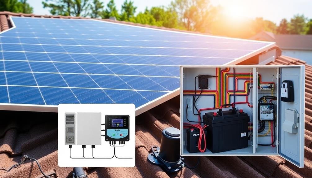
When examining solar panel wiring diagrams, you'll encounter three key components.
First, you'll see symbols and notations representing various electrical elements.
You'll also find connections and pathways showing how these elements link together.
Symbols and Notations
Understanding a solar panel wiring diagram's symbols and notations is essential for anyone looking to install or troubleshoot a solar power system. You'll encounter various symbols representing different components, each with a specific meaning.
Solar panels are typically depicted as rectangles with a plus and minus sign, while batteries are shown as two parallel lines. Inverters, charge controllers, and fuses have their own unique symbols.
You'll also see lines representing wires, with different colors or labels indicating their purpose. Red often denotes positive connections, while black represents negative. Dotted lines might indicate alternative connections or optional components. Numbers next to wires can show voltage or amperage ratings.
It's vital to understand notations for series and parallel connections. Series connections are usually shown with components in a line, while parallel connections are depicted side by side.
You'll also find notes about wire gauge, circuit breaker ratings, and grounding requirements.
Pay attention to any legends or keys provided, as they'll explain specific symbols used in the diagram. By familiarizing yourself with these symbols and notations, you'll be better equipped to interpret and work with solar panel wiring diagrams effectively.
Connections and Pathways
Having grasped the symbols and notations, you'll now focus on the connections and pathways in a solar panel wiring diagram. These elements show how components are linked and how electricity flows through the system. You'll see lines representing wires, with arrows indicating the direction of current flow. Junctions where wires meet are vital points to understand, as they often represent connections between different components.
| Connection Type | Description |
|---|---|
| Series | Increases voltage |
| Parallel | Increases current |
| String | Multiple panels in series |
| Array | Multiple strings in parallel |
| Combiner box | Joins multiple strings |
Pay attention to the thickness of lines, as they often indicate wire gauge. Thicker lines usually represent larger wires capable of handling higher currents. You'll also notice different colors used for positive, negative, and ground wires. Understanding these connections and pathways is important for troubleshooting, maintenance, and system expansion. They'll help you identify potential bottlenecks, guarantee proper load distribution, and optimize your solar panel system's performance. By mastering these elements, you'll be better equipped to interpret and work with solar panel wiring diagrams effectively.
Equipment and Devices
The heart of any solar panel wiring diagram lies in its equipment and devices. These components are vital for understanding how your solar power system functions.
You'll find several key elements represented in a typical diagram:
Solar panels are the primary energy generators, converting sunlight into electricity. Charge controllers regulate the flow of electricity from the panels to the batteries, preventing overcharging. Batteries store the energy for later use, while inverters convert DC power to AC power for household appliances.
You'll also see circuit breakers and fuses, which protect your system from electrical surges. Disconnect switches allow you to isolate parts of the system for maintenance or emergencies. Grounding equipment guarantees safety by providing a path for excess electricity.
Meters and monitoring devices help you track your system's performance. Junction boxes and combiner boxes connect multiple solar panels or strings. Finally, you'll find wiring connectors and cables that link all these components together.
Understanding these elements and their symbols in your wiring diagram is essential for proper installation, maintenance, and troubleshooting of your solar power system.
It's the key to confirming your setup operates efficiently and safely.
Series Vs Parallel Connections
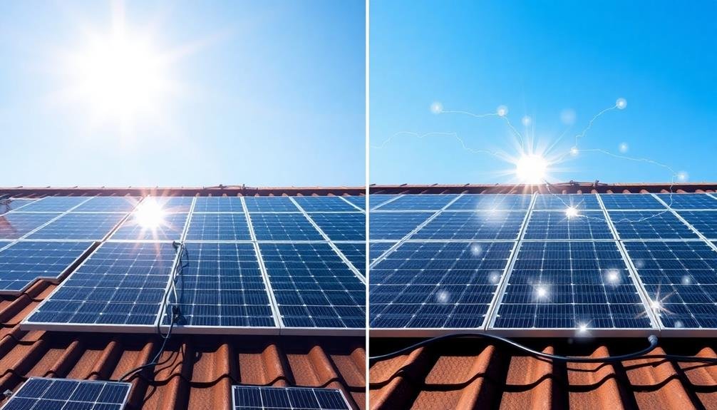
When designing your solar panel system, you'll need to understand the differences between series and parallel connections.
Series connections increase voltage while parallel connections increase current, both of which affect your system's overall power output.
Your choice between these connection types will have significant implications for your system's design, including equipment selection and performance characteristics.
Voltage and Current Differences
Understanding the differences between series and parallel connections is essential when wiring solar panels. In a series connection, you'll find that the voltage increases while the current remains constant. When you connect panels in series, you're adding up their voltages, which can be useful for meeting the input requirements of certain inverters or charge controllers.
On the other hand, parallel connections increase the current while maintaining the same voltage across all panels. This configuration is ideal when you need to boost the overall power output without changing the system voltage. It's particularly useful for larger systems or when you want to maintain performance even if one panel is shaded.
You'll need to evaluate your specific energy needs and equipment specifications when deciding between series and parallel connections. Series wiring is often preferred for its simplicity and reduced wire thickness requirements, but it can be more vulnerable to shading issues.
Parallel wiring offers better performance in partial shading conditions but requires thicker wires to handle the increased current. By understanding these voltage and current differences, you can design a more efficient and reliable solar panel system tailored to your needs.
Power Output Considerations
Power output is a key factor when deciding between series and parallel connections for your solar panel system. When you connect panels in series, you'll increase the voltage while maintaining the same current. This setup is ideal for systems with long wire runs or when you need to match a higher inverter input voltage.
Conversely, parallel connections increase current while keeping voltage constant, which is useful for systems with lower voltage requirements or when you want to maintain power output even if one panel is shaded.
Consider these points when evaluating power output for your solar panel wiring:
- Series connections offer higher efficiency over long distances
- Parallel connections provide better performance in partial shading
- Voltage limitations of charge controllers and inverters affect your choice
- System scalability differs between series and parallel configurations
- Power loss calculations vary based on connection type
You'll need to balance these factors with your specific system requirements.
System Design Implications
Three key system design implications arise when choosing between series and parallel connections for your solar panel setup.
First, voltage and current considerations greatly impact your inverter selection. In series connections, you'll see higher voltages but consistent current, while parallel connections maintain voltage but increase current. This affects the type and capacity of inverter you'll need to handle your system's output efficiently.
Second, the wiring complexity and cost differ between these configurations. Series connections typically require less wiring, as panels are linked end-to-end. Parallel setups, however, need more complex wiring arrangements and often additional components like combiner boxes, potentially increasing your installation costs.
Lastly, system performance and reliability are influenced by your connection choice. Series-connected panels are more susceptible to performance drops if one panel is shaded or malfunctions, as it affects the entire string. Parallel configurations offer better resilience in such scenarios, as each panel operates more independently.
You'll need to weigh these factors against your specific installation environment, budget constraints, and performance expectations to determine the best wiring configuration for your solar panel system.
Calculating System Voltage and Current

How do you determine the ideal voltage and current for your solar panel system? It's essential to calculate these values accurately to guarantee your system performs at its best and safely.
You'll need to take into account your energy needs, available space, and equipment specifications.
To calculate system voltage and current:
- Determine your daily energy consumption in watt-hours
- Assess the peak sun hours in your location
- Calculate the required array wattage
- Choose the number and type of solar panels
- Decide on series or parallel connections
Your system voltage affects the efficiency of power transmission and the selection of inverters and charge controllers. Higher voltages reduce power losses over long distances but require more panels in series.
Lower voltages are safer and more suitable for smaller systems.
Current calculations help you size wires and circuit breakers correctly. You'll need to account for the short-circuit current of your panels and any potential surges.
Proper Wire Sizing and Selection

When selecting wires for your solar panel system, you'll need to take into account three essential factors.
First, calculate the ampacity requirements to guarantee your wires can safely handle the current flow.
Next, account for voltage drop to maintain efficiency over long distances.
Calculating Ampacity Requirements
For a safe and efficient solar panel system, calculating the proper ampacity requirements is vital. Ampacity refers to the maximum current a wire can safely carry without overheating.
When you're designing your solar panel wiring diagram, you'll need to ascertain the ampacity for each wire in your system.
To calculate ampacity requirements, you'll need to take into account several factors:
- The maximum current your solar panels can produce
- The voltage of your system
- The length of your wire runs
- The ambient temperature where the wires will be installed
- Any derating factors that may apply
Once you've gathered this information, you can use the National Electrical Code (NEC) tables to determine the minimum wire size needed.
It's important to select a wire with an ampacity rating that exceeds your calculated requirements by at least 25% to guarantee safety and account for potential increases in current.
Voltage Drop Considerations
Voltage drop across your solar panel wiring system can greatly impact the overall performance and efficiency of your setup.
It's vital to take this factor into account when selecting the appropriate wire size for your solar installation. As electricity flows through wires, it encounters resistance, which causes voltage to decrease over distance. This drop can result in reduced power output and system inefficiency.
To minimize voltage drop, you'll need to choose wires with adequate thickness (gauge) based on the current flow and length of your wiring runs. A general rule of thumb is to keep voltage drop below 2% for peak performance.
You can calculate the required wire size using voltage drop calculators or formulas that account for factors such as wire material, temperature, and current load.
Remember that larger wire sizes (smaller gauge numbers) offer less resistance and lower voltage drop but come at a higher cost. It's important to strike a balance between performance and budget.
Additionally, think about using higher voltage systems, such as 24V or 48V, to reduce current flow and minimize voltage drop.
Insulation and Durability
Selecting the right wire insulation and durability is vital for guaranteeing the longevity and safety of your solar panel system. When choosing wires for your solar installation, you'll need to take into account factors like UV resistance, temperature tolerance, and moisture protection. These elements are essential in protecting your wiring from environmental damage and preventing electrical faults.
To verify you're selecting the right wires for your solar panel system, take into account the following:
- UV-resistant insulation to prevent degradation from sunlight exposure
- Temperature rating suitable for both hot and cold conditions
- Moisture-resistant properties to guard against water ingress
- Abrasion-resistant outer jacket for mechanical protection
- Flame-retardant materials for added safety
You'll want to opt for wires specifically designed for outdoor use, such as USE-2 or PV Wire. These types of cables are built to withstand harsh environmental conditions and maintain their integrity over time.
Don't skimp on wire quality, as it's a significant component of your solar panel system's overall performance and safety. By investing in high-quality, durable wiring, you'll reduce the risk of system failures and guarantee your solar panels continue to operate efficiently for years to come.
Inverter Integration in Diagrams
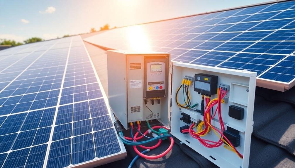
Inverter placement is a significant element in solar panel wiring diagrams. When you're designing your solar power system, you'll need to include the inverter's location and connections accurately. The inverter converts DC electricity from your solar panels into AC electricity for your home appliances, so its integration is critical for system functionality.
In your wiring diagram, you'll typically show the inverter connected between the solar array and your home's electrical panel. You'll need to illustrate how the DC power from the panels flows into the inverter and how the AC power exits to your home's circuits.
Don't forget to include safety components like disconnect switches and grounding connections. If you're using microinverters or power optimizers, you'll need to show their connections at each panel. This differs from a central inverter setup, where all panels connect to a single unit.
Your diagram should also indicate wire sizes, fuse ratings, and any necessary combiner boxes. By clearly depicting inverter integration, you'll guarantee proper installation and help troubleshoot potential issues in the future.
Battery Bank Configuration Considerations

For off-grid or hybrid solar systems, battery bank configuration is a fundamental aspect of your wiring diagram. You'll need to carefully consider how you'll connect your batteries to guarantee peak performance and longevity. The configuration you choose will depend on your system's voltage requirements and the desired capacity.
When planning your battery bank, keep these key points in mind:
- Series connections increase voltage
- Parallel connections increase capacity
- Series-parallel combinations offer both higher voltage and capacity
- Battery types should never be mixed within a bank
- All batteries in a bank should have the same age and capacity
Your wiring diagram should clearly show how the batteries are interconnected and how they connect to the charge controller and inverter.
It's essential to use appropriately sized cables and fuses to protect your battery bank from potential shorts or overloads.
Remember that battery banks require regular maintenance and monitoring, so make sure your diagram includes any necessary disconnects or safety features for easy servicing.
Grounding and Surge Protection

A essential aspect of any solar panel wiring diagram is proper grounding and surge protection. You'll need to guarantee your system is safely grounded to protect against electric shock and fire hazards. Grounding also helps dissipate static electricity and provides a path for lightning strikes to be safely directed into the earth.
Your wiring diagram should clearly show the grounding points for all components, including panels, inverters, and battery banks. You'll want to use appropriately sized grounding wires and connect them to a grounding rod driven deep into the soil.
Don't forget to include surge protection devices in your diagram. These are important for safeguarding your expensive solar equipment from voltage spikes caused by lightning or grid fluctuations.
Place surge protectors at key points in your system, such as between the solar panels and charge controller, and between the inverter and main electrical panel. Make sure you're using surge protectors rated for DC and AC currents as appropriate.
Troubleshooting Common Wiring Issues

Electrical gremlins can plague even the most carefully designed solar panel systems. When troubleshooting wiring issues, you'll need to systematically check connections, components, and system performance.
Start by reviewing your wiring diagram to verify everything's connected correctly. Then, use a multimeter to test voltage and current at various points in the system.
Common wiring issues you might encounter include:
- Loose connections causing intermittent power loss
- Reversed polarity on battery or panel connections
- Undersized wires leading to voltage drops
- Corroded terminals resulting in poor conductivity
- Damaged insulation causing short circuits
If you're experiencing reduced power output, check for shading on panels or dirty surfaces.
Inspect all junction boxes and connectors for signs of water ingress or thermal damage. Don't forget to verify that your charge controller and inverter settings are correct for your system configuration.
When troubleshooting, always prioritize safety. Turn off the system before working on any wiring, and if you're unsure about a problem, consult a professional.
Optimizing System Performance Through Diagrams
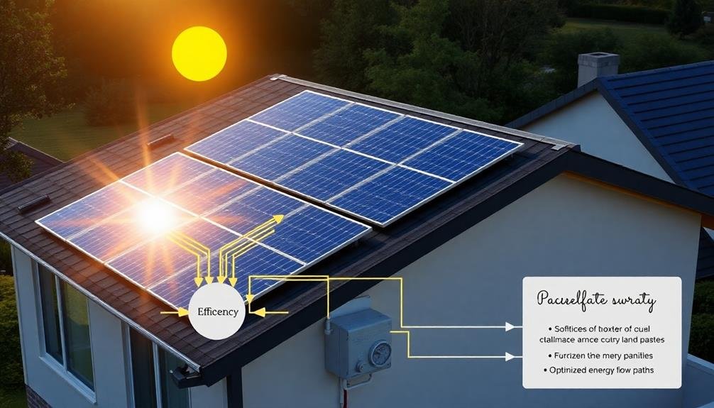
While troubleshooting helps resolve issues, enhancing your solar panel system's performance begins with a well-designed wiring diagram. These diagrams serve as blueprints for your system, allowing you to visualize and plan the most efficient layout. By carefully mapping out your panel connections, you'll minimize voltage drops and maximize power output.
A well-crafted diagram helps you determine the best string size and configuration for your specific inverter and panel specifications. You'll be able to guarantee proper voltage and current levels throughout the system, reducing the risk of underperformance or equipment damage.
Additionally, you can plan for future expansions by incorporating spare capacity into your initial design. Wiring diagrams also aid in balancing loads across multiple strings, ensuring even wear on components and consistent power production.
They'll help you identify the best locations for disconnects, fuses, and other safety devices, enhancing system protection. By using diagrams to enhance cable routing, you'll minimize line losses and improve overall system efficiency.
Ultimately, a thorough wiring diagram enables you to create a solar panel system that operates at peak performance, maximizing your energy production and return on investment.
Frequently Asked Questions
How Often Should Solar Panel Wiring Diagrams Be Updated or Revised?
You should update your solar panel wiring diagrams whenever you make changes to your system. It's essential to revise them after adding new panels, replacing components, or modifying the layout. Regular reviews guarantee your diagrams remain accurate and useful.
Can I Use a Generic Wiring Diagram for Different Solar Panel Brands?
You shouldn't use generic wiring diagrams for different solar panel brands. Each brand has unique specifications and requirements. You'll need to consult brand-specific diagrams to guarantee proper installation, best performance, and safety for your solar panel system.
Are There Software Tools Available for Creating Solar Panel Wiring Diagrams?
Yes, you'll find several software tools for creating solar panel wiring diagrams. Popular options include AutoCAD, SketchUp, and specialized solar design software like PVsyst or Aurora. These tools help you design accurate, professional-looking diagrams for your solar installations.
How Do Local Building Codes Affect Solar Panel Wiring Diagram Requirements?
Your local building codes greatly impact solar panel wiring diagram requirements. They'll dictate specific safety standards, grounding methods, and electrical specifications you must follow. You'll need to guarantee your diagrams comply with these regulations for permit approval.
What Certifications Should I Look for in Professionals Who Create Wiring Diagrams?
You should look for professionals certified as Electrical Engineers, Licensed Electricians, or Certified Solar PV Installers. They'll have NABCEP (North American Board of Certified Energy Practitioners) certification, which is highly respected in the solar industry.
In Summary
You've now grasped the importance of solar panel wiring diagrams. They're essential for safety, efficiency, and troubleshooting. By understanding these diagrams, you'll confidently plan your system, avoid costly mistakes, and optimize performance. Remember, proper wiring guarantees your solar setup operates at its best. Don't underestimate the power of a well-designed diagram – it's your roadmap to successful solar energy integration. Keep learning and stay safe as you harness the sun's power for your energy needs.


Leave a Reply